
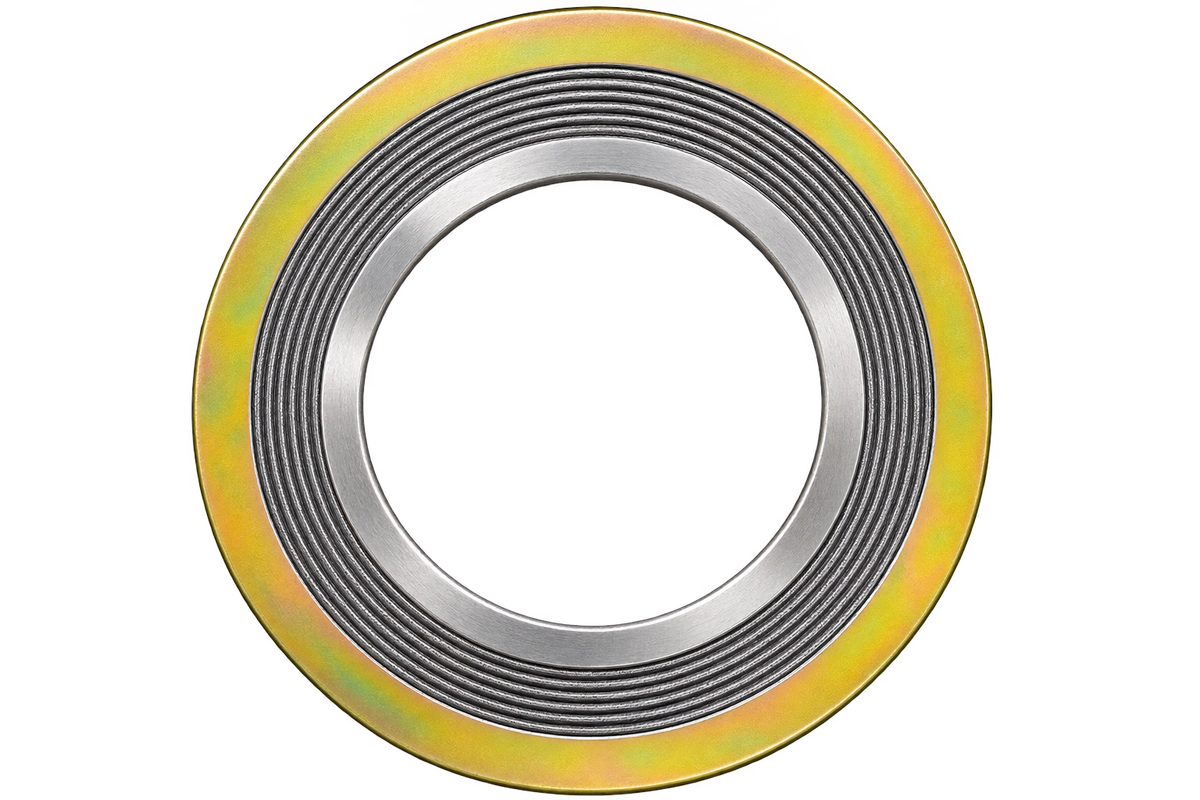
Bore-side support and external location, specified together. sales@ferrobend.com +91-8369719424

Combined ring arrangement

Spiral Wound Gasket With Inner & Outer Ring

A spiral-wound sealing element between a solid inner ring and an outer guide ring. Match all component diameters and materials to the flange and service.

Spiral Wound Gasket With Inner & Outer Ring, showing the winding and locating arrangement

THE CONSTRUCTION

Support at the bore.
Location at the outside.

The outer ring locates the assembly while the inner ring supports the winding at the bore. The metal-and-filler winding between them provides the active sealing element.

Specify winding, filler, inner-ring and outer-ring materials individually. Ring diameters, flange facing and the applicable inner-ring requirements must agree with the selected dimensional reference.

Compare all six configurations
ArrangementInner ring + winding + outer ring
Location / supportExternal centering
Design requirementBore-side support

TECHNICAL REFERENCE

Standards & material specifications

Match the construction, joint geometry and component materials.

Dimensions & joint requirements

Spiral Wound Gasket With Inner & Outer Ring dimensional and joint references
ASME B16.20Covered spiral-wound materials, dimensions, tolerances and marking. Match the referenced flange and required ring arrangement.
EN 1514-2Spiral-wound gaskets for covered PN-designated steel flange joints. Verify the flange and specified edition.
EN 12560-2Spiral-wound dimensions for covered Class-designated steel flange joints. Confirm the size, class and construction.

An inner ring supports the winding against inward buckling. Check bore clearance and the specified ring requirements. A flange Class designation does not establish the complete assembly’s operating-pressure limit.

Component material requirements

Spiral Wound Gasket With Inner & Outer Ring material references
Metal windingFor a 316L stainless winding, specify UNS S31603 strip and the ordered material specification, such as ASTM A240/A240M. Select the filler separately.
Soft fillerFlexible graphite or PTFE are established options. Specify the actual grade and verify chemical compatibility, oxidation conditions and service limits.
Inner / outer ringsSpecify each ring grade and finish separately. The bore-side ring faces different conditions from the outer locating ring; they need not have the same specification.

Material capability does not establish complete-joint capability. Confirm the standard edition, component marking and service conditions; illustration colours are not material identification. Construction references: Flexitallic selection guide · Teadit construction guide.

UNDERSTAND THE ARRANGEMENT

Construction details that matter.

Illustrative views of this configuration. Geometry, proportions and colours are schematic; use the specified standard or approved drawing.

Inner and outer rings — Spiral Wound Gasket With Inner & Outer RingSchematic construction detail. Colour, proportions and any illustrated hole count do not specify a supplied gasket.Outer ringInner ringWinding
01 / Construction detail

Inner and outer rings

The two solid rings have distinct roles: external positioning and bore-side winding support.

Winding between the rings — Spiral Wound Gasket With Inner & Outer RingSchematic construction detail. Colour, proportions and any illustrated hole count do not specify a supplied gasket.Profiled metal + soft fillerInner ringOuter ringIllustrative uncompressed radial section
02 / Construction detail

Winding between the rings

The wound element provides the seal. Its initial thickness and seating behaviour differ from the solid rings.

Diameter checks — Spiral Wound Gasket With Inner & Outer RingSchematic construction detail. Colour, proportions and any illustrated hole count do not specify a supplied gasket.Outer-ring ODWinding ODWinding IDInner-ring ID
03 / Construction detail

Diameter checks

Verify inner-ring ID, winding ID, winding OD and outer-ring OD against the same flange reference, including the correct series where relevant.

Define the Right Spiral Wound Configuration

Share the flange or joint drawing, ring arrangement, component materials, service conditions and quantity.

Request a Quote