
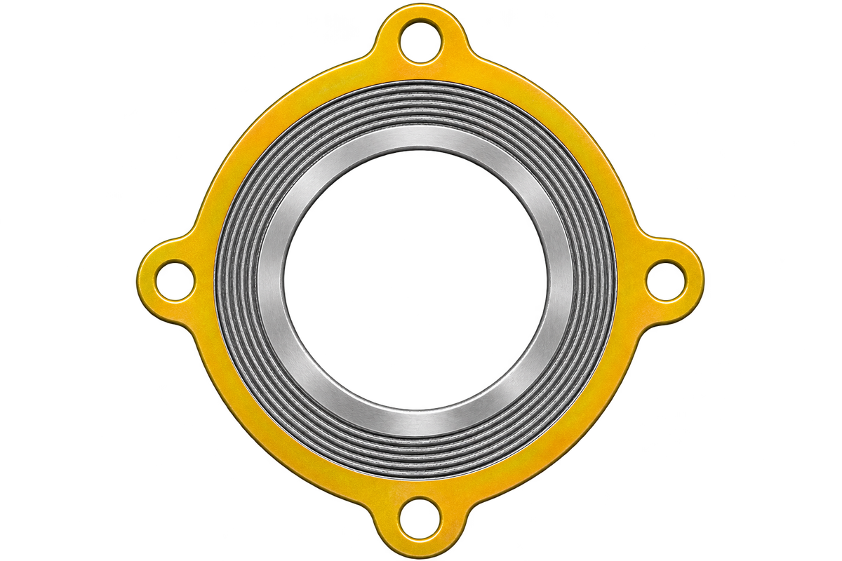
Locate the seal with drawing-defined tabs, lugs or ears. sales@ferrobend.com +91-8369719424

Drawing-specific locating features

Spiral Wound Gasket With Centering Device

A spiral-wound assembly with locating tabs or lugs defined by the joint drawing. The device positions the seal; the winding and support rings require separate specification.

Spiral Wound Gasket With Centering Device, showing the winding and locating arrangement

THE CONSTRUCTION

Locating features.
A drawing-defined assembly.

This catalog entry refers to the illustrated lugged locating arrangement. Tabs or ears extend beyond the circular assembly to help position or retain it in its intended joint.

The term centering device can also mean an ordinary outer guide ring. Here, the drawing must identify the actual device, its attachment or integral construction, hole pattern and any inner-ring requirement.

Compare all six configurations
ArrangementDrawing-specific construction
Location / supportLocating tabs / lugs
Design requirementRing arrangement specified separately

TECHNICAL REFERENCE

Standards & material specifications

Match the construction, joint geometry and component materials.

Dimensions & joint requirements

Spiral Wound Gasket With Centering Device dimensional and joint references
Approved assembly drawingControls tab count, angular positions, projection, holes or slots, carrier dimensions and attachment details.
ASME B16.20Apply relevant winding and ring requirements only where the specified construction falls within scope. Custom lugs are not automatically a standard dimensional type.
Equipment specificationConfirm fit, assembly access and compression control with the equipment designer. Locating features alone do not define a compression stop.

The four-lug illustration is an example, not a mandatory pattern. Do not infer bolt-hole count, flange suitability or service limits from the picture.

Component material requirements

Spiral Wound Gasket With Centering Device material references
Metal windingFor a 316L stainless winding, specify UNS S31603 strip and the ordered material specification, such as ASTM A240/A240M. Select the filler separately.
Soft fillerFlexible graphite or PTFE are established options. Specify the actual grade and verify chemical compatibility, oxidation conditions and service limits.
Carrier & locating featuresSpecify material, thickness, corrosion protection and any attachment method. Identify a separate inner ring where the approved drawing requires one.

Material capability does not establish complete-joint capability. Confirm the standard edition, component marking and service conditions; illustration colours are not material identification. Construction references: Flexitallic selection guide · Garlock retention guidance.

UNDERSTAND THE ARRANGEMENT

Construction details that matter.

Illustrative views of this configuration. Geometry, proportions and colours are schematic; use the specified standard or approved drawing.

Locating lugs — Spiral Wound Gasket With Centering DeviceSchematic construction detail. Colour, proportions and any illustrated hole count do not specify a supplied gasket.Locating lugWound sealExample four-lug arrangement
01 / Construction detail

Locating lugs

Tabs or ears provide the drawing-defined locating feature. Their number, size and position must match the equipment.

Winding and carrier — Spiral Wound Gasket With Centering DeviceSchematic construction detail. Colour, proportions and any illustrated hole count do not specify a supplied gasket.Profiled metal + soft fillerInner ringCarrier / outer ringIllustrative uncompressed radial section
02 / Construction detail

Winding and carrier

The sealing element remains separate from its locating carrier. Specify support rings and compression control independently.

Lug pattern — Spiral Wound Gasket With Centering DeviceSchematic construction detail. Colour, proportions and any illustrated hole count do not specify a supplied gasket.Hole diameterPitch circleCount, clocking and dimensions from drawing
03 / Construction detail

Lug pattern

State tab projection, angular spacing, hole or slot dimensions and attachment details. The example pattern is not a universal standard.

Define the Right Spiral Wound Configuration

Share the flange or joint drawing, ring arrangement, component materials, service conditions and quantity.

Request a Quote