
Machined grooves. Clearly specified metal contact. sales@ferrobend.com +91-8369719424

Metallic / Grooved profile

Solid Grooved Metal Gasket

A solid metal ring with machined concentric grooves. Define the bare-metal profile, contact geometry and material condition for the joint.

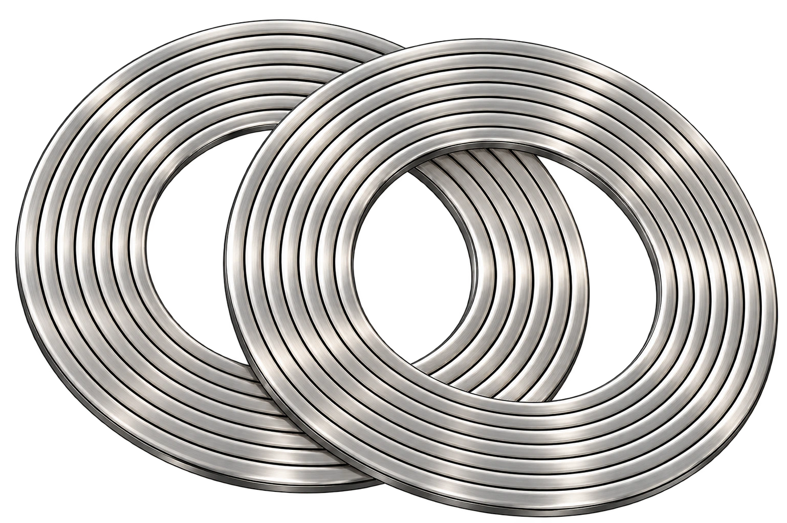
Solid Grooved Metal Gasket product illustration

THE CONSTRUCTION

Machined grooves. Metal-to-metal contact.

A solid grooved metal gasket has a metallic body with grooves machined into its sealing faces. In the bare construction described here, the metal lands contact the mating joint directly.

A grooved core covered with soft graphite or PTFE facing belongs to the soft-faced Kammprofile construction. The two should not be treated as interchangeable.

ClassificationMetallic
ConstructionBare metal profile
SpecificationStandard or approved drawing

TECHNICAL REFERENCE

Standards & material specifications

Specify the joint reference, profile and material condition together.

Dimensions & joint requirements

Solid Grooved Metal Gasket dimensional and joint references
EN 1514-4Dimensions of corrugated, flat and grooved metallic gaskets for PN-designated flange joints within its scope.
EN 12560-4Inside-bolt-circle metallic gaskets for covered Class-designated steel flange joints. Verify the flange, size and specified edition.
Profile drawingSpecify groove form, pitch, depth, land width and remaining core thickness. Manufacturer profile codes are not universal geometry standards.

Reference standards apply only within their scope. Dimensional conformity alone does not demonstrate sealing suitability or certify a supplied product.

Material specification references

Solid Grooved Metal Gasket material requirements
ASTM A240/A240MA raw-material reference for stainless plate, sheet and strip. Specify the grade and delivery condition separately.
ASTM A276/A276MA raw-material reference for stainless bars and shapes. Applicability depends on the stock form and ordered condition.
Surface & hardnessSpecify finished condition and contact surfaces against the flange design. Hardness and seating load require joint-specific review.

Raw-material compliance does not establish assembly pressure or temperature limits. Confirm the specified edition and service requirements.

UNDERSTAND THE PROFILE

The details that define the joint.

Three specification details within this gasket family. Illustrations are schematic and not to scale.

Grooved section — Solid Grooved Metal GasketIllustrative grooved section view. The highlighted geometry corresponds to the specification detail explained below; dimensions and colours are schematic.Concentric machined groovesSolid metal core; no soft facing
01 / Profile detail

Grooved section

Define groove depth and remaining core thickness. Control both dimensions on the approved drawing.

Contact lands — Solid Grooved Metal GasketIllustrative contact lands view. The highlighted geometry corresponds to the specification detail explained below; dimensions and colours are schematic.Mating flange faceMetal lands contact the flanges
02 / Profile detail

Contact lands

Bare metal lands contact the flange. Verify mating surface condition and the required seating load.

Profile control — Solid Grooved Metal GasketIllustrative profile control view. The highlighted geometry corresponds to the specification detail explained below; dimensions and colours are schematic.PitchdSealing widthSpecify depth d, land width and core thickness
03 / Profile detail

Profile control

Record pitch, land width, finish and tolerances. Adding a soft facing changes the specified construction.

Specify Your Solid Grooved Metal Gasket

Share the joint drawing or standard, dimensions, alloy, operating conditions and quantity.

Request a Quote