
Define the corrugation. Match the complete joint. sales@ferrobend.com +91-8369719424

Metallic / Corrugated profile

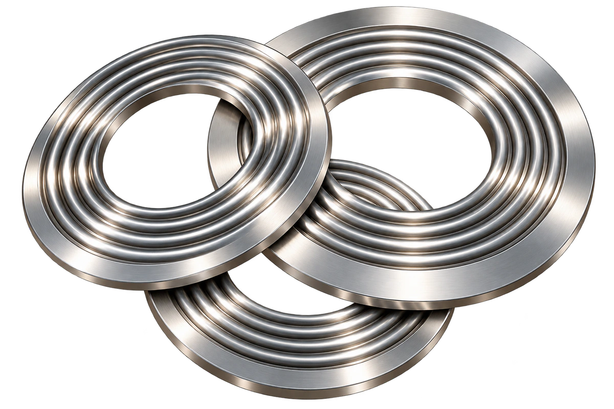
Corrugated Solid Metal Gasket

An all-metal gasket formed with concentric corrugations. Specify the alloy, sheet thickness and corrugation geometry for the mating flange.

Corrugated Solid Metal Gasket product illustration

THE CONSTRUCTION

Formed metal. Defined sealing crests.

A corrugated solid metal gasket is a metal sheet formed into a series of concentric waves. The crests provide the initial contact regions when the joint is assembled.

This page covers bare all-metal construction. Adding graphite, PTFE or another soft facing creates a different construction with different seating and service behaviour.

ClassificationMetallic
ConstructionBare metal profile
SpecificationStandard or approved drawing

TECHNICAL REFERENCE

Standards & material specifications

Specify the joint reference, profile and material condition together.

Dimensions & joint requirements

Corrugated Solid Metal Gasket dimensional and joint references
EN 1514-4Dimensions of corrugated, flat and grooved metallic gaskets for PN-designated flange joints within its scope.
EN 12560-4Inside-bolt-circle metallic gaskets for covered Class-designated steel flange joints. Verify the flange, size and specified edition.
Joint geometryConfirm ID/OD, sheet thickness, formed height and corrugation details. Nonstandard joints require an approved drawing.

Reference standards apply only within their scope. Dimensional conformity alone does not demonstrate sealing suitability or certify a supplied product.

Material specification references

Corrugated Solid Metal Gasket material requirements
ASTM A240/A240MA raw-material reference for stainless plate, sheet and strip. Specify the grade and delivery condition separately.
Metal selectionSpecify alloy and condition for the fluid and joint. Sheet thickness and forming requirements must match the selected construction.
Assembly reviewCheck flange condition, seating load and compression limits. Do not infer performance from the metal grade alone.

Raw-material compliance does not establish assembly pressure or temperature limits. Confirm the specified edition and service requirements.

UNDERSTAND THE PROFILE

The details that define the joint.

Three specification details within this gasket family. Illustrations are schematic and not to scale.

Corrugated section — Corrugated Solid Metal GasketIllustrative corrugated section view. The highlighted geometry corresponds to the specification detail explained below; dimensions and colours are schematic.Continuous formed metal sheetRing view and enlarged radial section
01 / Profile detail

Corrugated section

Define sheet thickness separately from the overall formed height. These are different dimensions.

Sealing crests — Corrugated Solid Metal GasketIllustrative sealing crests view. The highlighted geometry corresponds to the specification detail explained below; dimensions and colours are schematic.Mating flange faceCrests contact the joint faces
02 / Profile detail

Sealing crests

Concentric crests contact the mating faces. Surface condition and specified assembly load affect sealing.

Formed geometry — Corrugated Solid Metal GasketIllustrative formed geometry view. The highlighted geometry corresponds to the specification detail explained below; dimensions and colours are schematic.Pitchht = metal sheet thicknessFormed height h is not sheet thickness t
03 / Profile detail

Formed geometry

Record corrugation pitch, depth, number of waves and usable sealing width on the joint drawing.

Specify Your Corrugated Solid Metal Gasket

Share the joint drawing or standard, dimensions, alloy, operating conditions and quantity.

Request a Quote